Solderless CH341A/B Fix: 5V to 3.3V Data Lines
Heads up: This post is targeting the most popular programmer, the CH341A/B Black model. There are two versions of this model floating around. The most common, older version has capacitor C4 on the opposite side of the crystal oscillator, and the other, newer version has the capacitor C4 on the same side as the crystal oscillator.
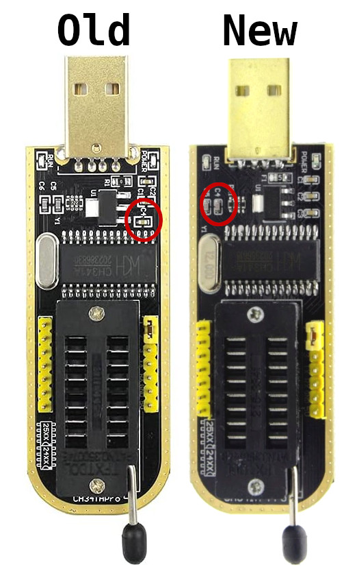
I am using the newer version to demonstrate this fix. It should work on the older version as well, but use your discretion.
The Problem
If you haven’t heard, there is a pretty bad issue with the popular CH341A/B flash programmers. Most versions will send 5 volts down the data lines, and most flash chips are only rated for 3.3 volts across their data lines. This is a problem–it means the majority of the time, you are operating your flash chips out of specification, which could result in bad reads and writes or a fried flash chip in the worst case.
Identifying the Issue
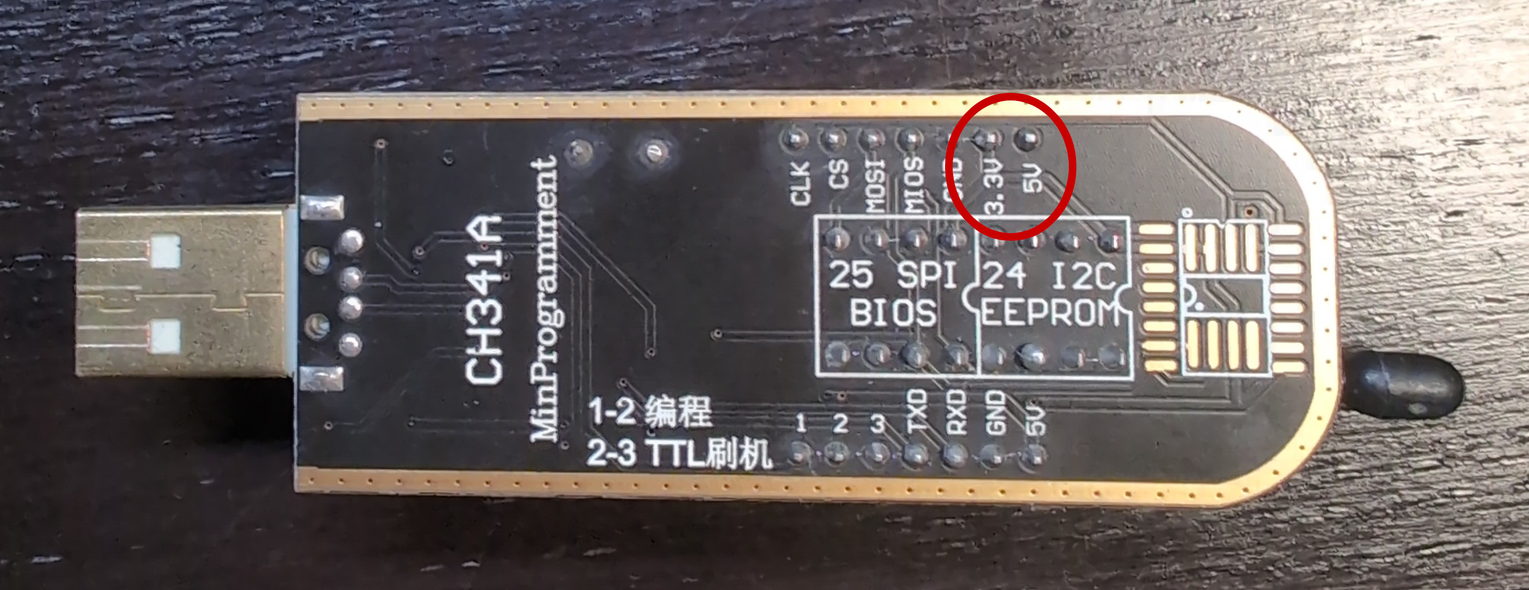
You can tell if your programmer is sending 5 volts down the data lines by measuring the voltage across them with a multimeter while the programmer is plugged in. Take a look at the pin-out diagram1 of the programmer:
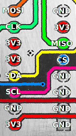
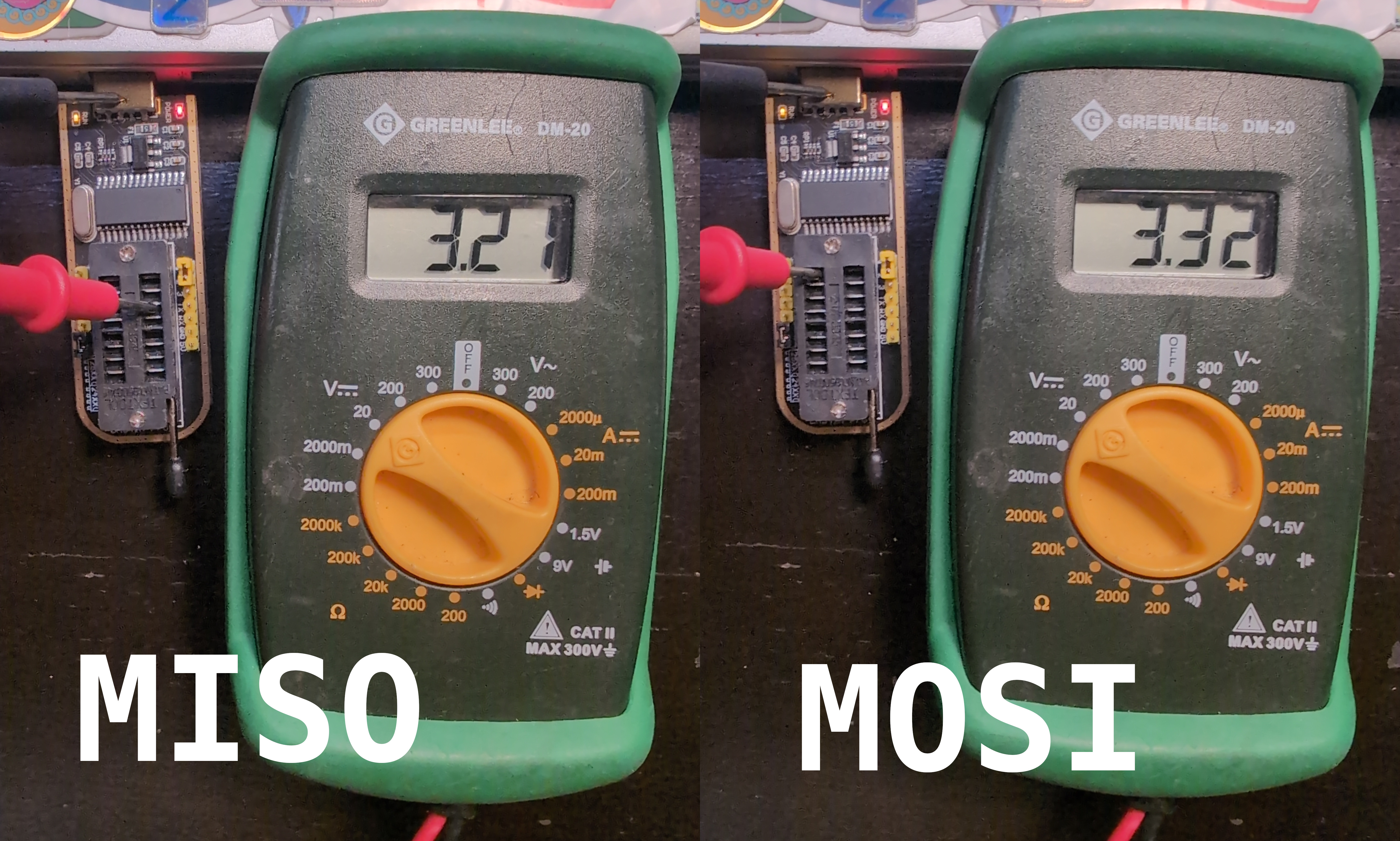
You’ll want to measure the voltage across pin 2, MISO (master in, slave out2), and pin 5, MOSI (master out, slave in). Here’s how that looks like on the real device:
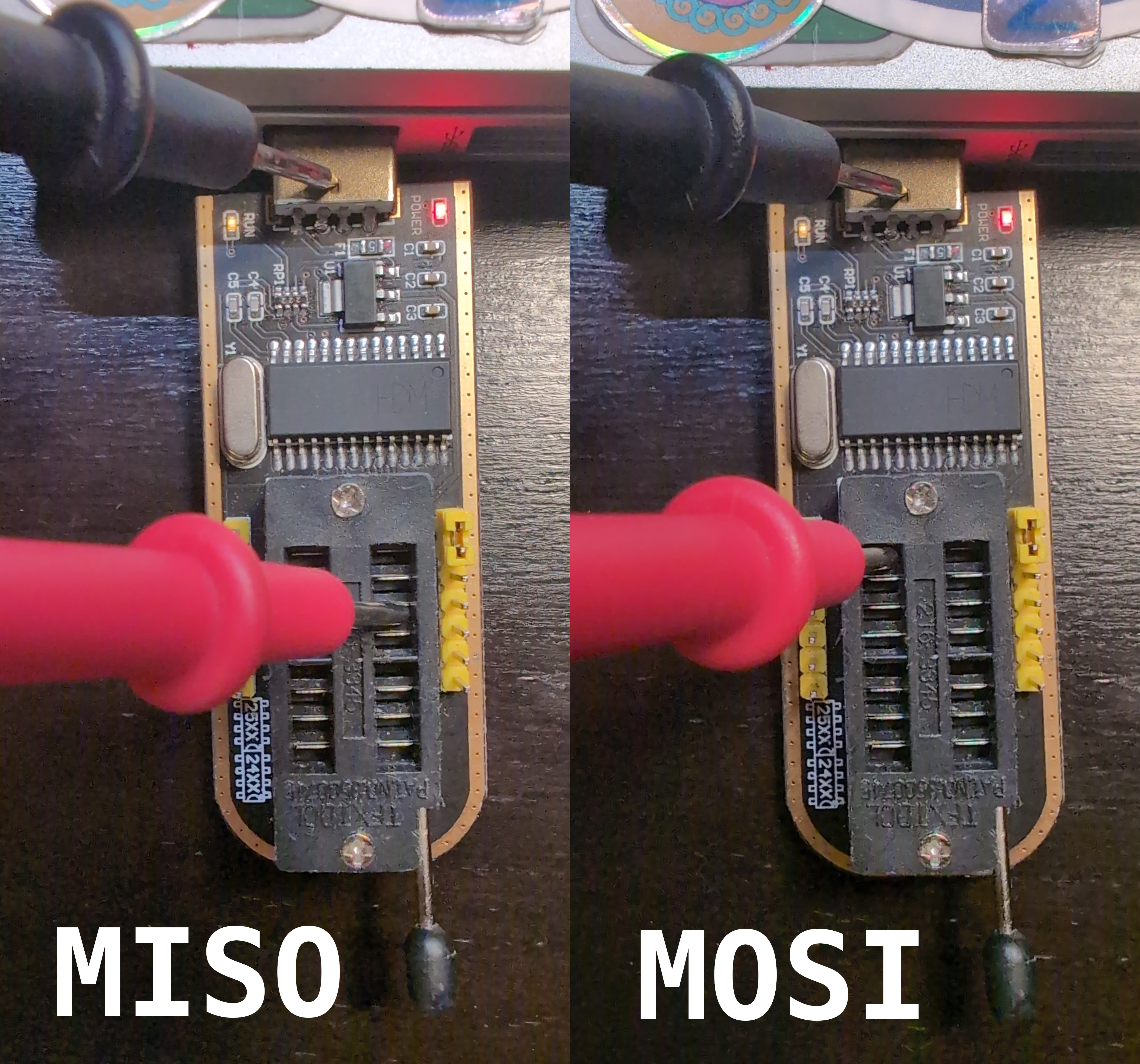
Plug the programmer into a powered USB port (a laptop will work fine), touch ground with the black multimeter probe (the USB plug works well), and the red probe to pin 2 and 5. If your programmer is faulty, the multimeter will read about 5 volts.
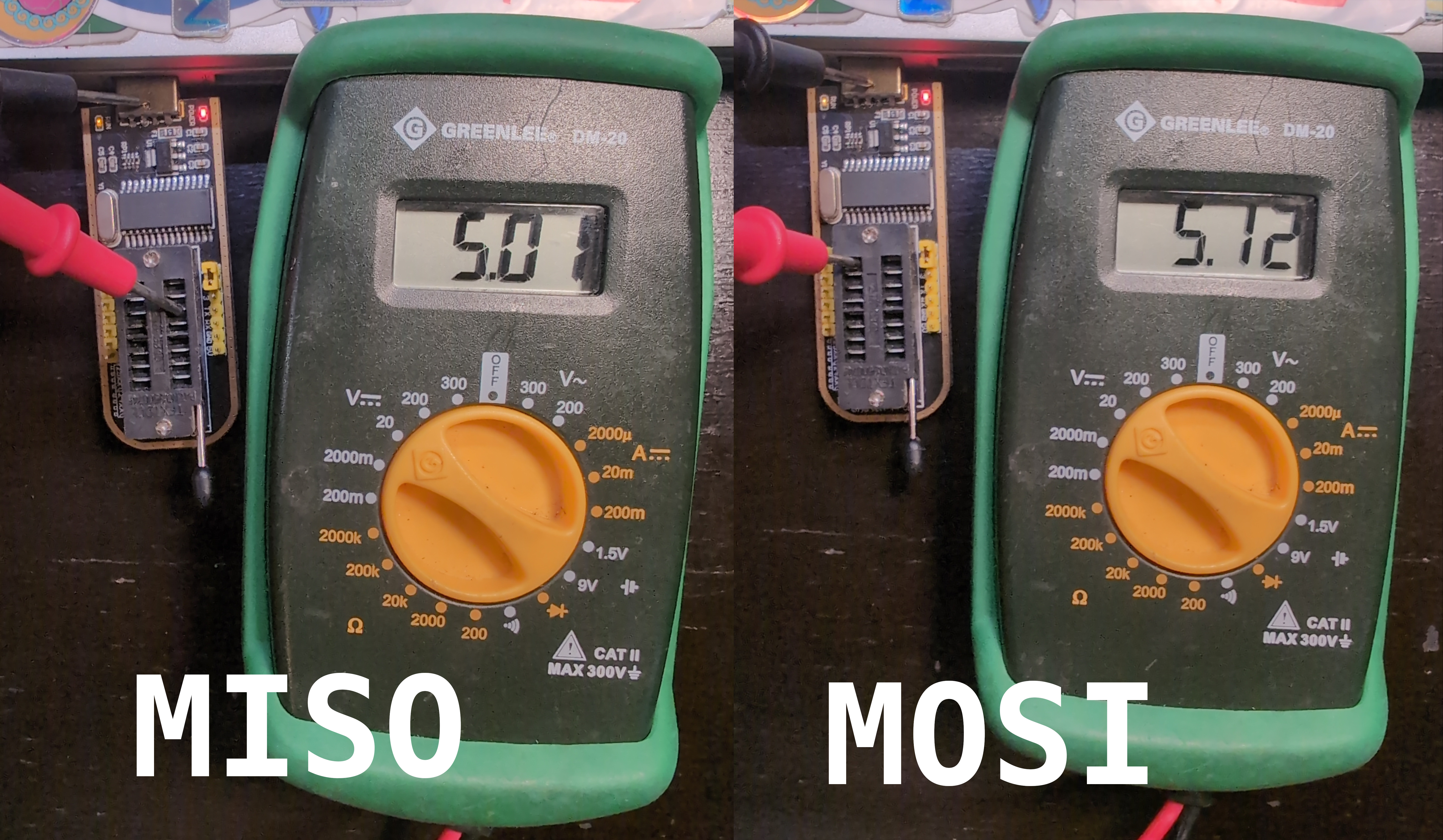
That’s no good!
The Fix
There are a number of existing fixes out there for this model. However, most fixes target the older version, and they typically entail lifting pins of the CH341A/B chip off the pads and wiring them to other pins of the AMS1117 chip and capacitor C4. It definitely doesn’t look the cleanest, and the new version of the black programmer places capacitor C4 on the other side of the board. While it might only be a change in naming convention, I don’t want to go through that effort for it not to work at all.
Which brings us to a clever fix that requires no soldering, just a sharp implement and a two-pin jumper. I did not come up with this–I found it in the depths of an electrical engineering forum3–but I thought it was so fantastic I had to share it.
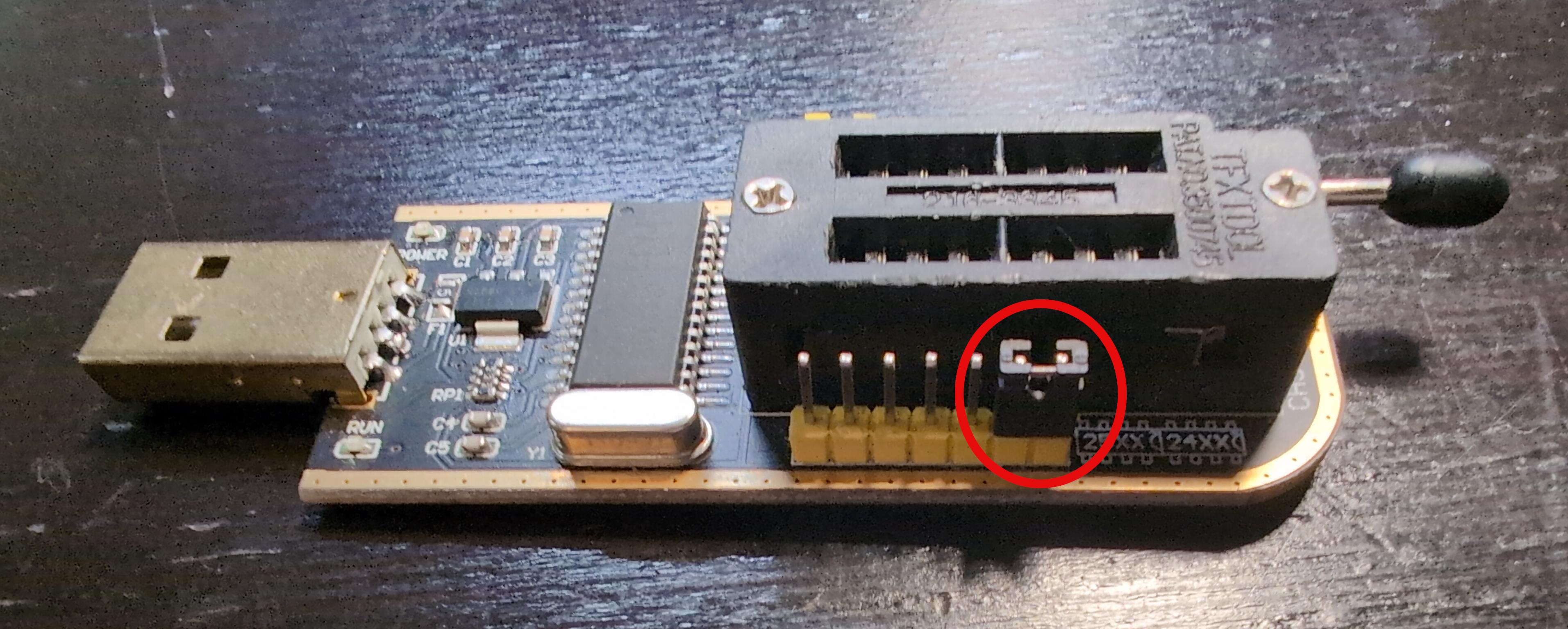
First, turn the programmer over. Scrape away a path through the trace on the left. You want to completely obliterate it so no current can flow across your cut. What we are doing is cutting the 5V line from the USB header.

Take a look at the far end of the programmer, and note the neighboring 3.3V and 5V pins.
Now, flip the programmer right-side-up and join those two pins with the jumper.
You have just replaced the 5 volt power supply with the 3.3 volt power supply on the data lines. The device should now function within specifications for most flash chips. You can verify it is working as intended by repeating the steps in the Identifying the Issue section. This time, your multimeter should read around 3.3 volts for both pins.
Congratulations, your CH341A/B programmer’s data lines are now operating at the proper 3.3 volts!
Thanks to Jake Little for his work reverse-engineering the programmer schematic: https://github.com/Upcycle-Electronics/CH341A-Pro ↩︎
I’d usually prefer different terminology over master/slave, but that’s what it’s called in the datasheet and this graphic. ↩︎
Thanks to RaceJay for their inventive fix: https://www.eevblog.com/forum/repair/ch341a-serial-memory-programmer-power-supply-fix/50/#msg3769994 ↩︎